Abstract: Taking an automotive engine crankcase as an example, this paper introduces the locations where leakage occurs in aluminum alloy die castings. Through the "bubble" test in sealing testing and sectioning inspection of the defective areas of the casting, it was determined that the leakage was caused by through-wall shrinkage cavities and porosity inside the casting. A cause analysis table was used to analyze the root causes of the shrinkage cavities, and mold optimization measures such as local pressurization, increased core cooling, and machining heat dissipation knurling on the cavity forming surface were adopted to effectively resolve the shrinkage cavity defects in the crankcase and improve the first-pass yield of aluminum alloy die castings.
Keywords: aluminum alloy die casting; shrinkage porosity; leakage; local pressurization; mold cooling
Die casting is a process in which molten metal is injected into a mold cavity at high pressure and high speed, then cooled and formed under high pressure to obtain a product. With the rapid development of the automotive industry, the demand for die-cast parts is also increasing. Most components such as automotive engine blocks, oil pans, cylinder head covers, front and rear end covers, as well as clutch housings and transmission housings for gearboxes, are produced as blanks by high-pressure die casting using aluminum-silicon alloys. Blanks obtained by the high-pressure die casting method—which is a near-net-shape process—require only a small amount of CNC machining afterward to obtain the final product.
1. Structure and Defect Types of Crankcase Bodies
Figure 1 shows a certain automotive engine crankcase housing, made of ADC12, with an overall casting profile dimension of 442 mm × 358 mm × 173 mm and a weight of approximately 4.5 kg. This product has a complex structure, with a general wall thickness of 3.0 mm and a local functional area wall thickness of 15–20 mm. Five faces of the housing require CNC machining to meet the product's dimensional accuracy and assembly requirements. The product's sealing performance requirements: cavity test pressure of 100 kPa, leakage rate less than 20 cm3/min; Area A has a 90° cross oil gallery hole with a diameter of 12 mm. The oil gallery hole requires a test pressure of 600 kPa and a leakage rate of less than 15 cm3/min。
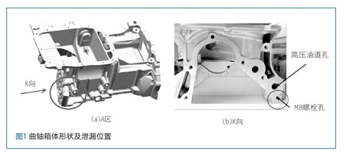
In actual production, after machining, the crankcase undergoes a sealing test. The cavity shows no leakage, but in the high-pressure oil gallery at a pressure of 600 kPa, 12% of the parts are scrapped due to excessive leakage. Statistical analysis was performed on the leakage values of the leaking parts, and the leakage values are distributed in the range of 15-30 cm3/min. To solve the leakage problem, the specific leak location must first be identified. A "bubble" test was performed on the part, and small bubbles were found seeping from the M8 hole in direction K as shown in Figure 1, confirming it as the leak point of the high-pressure oil passage.
2. Analysis of Causes of Crankshaft Housing Leakage
2.1 Leak Cause Investigation
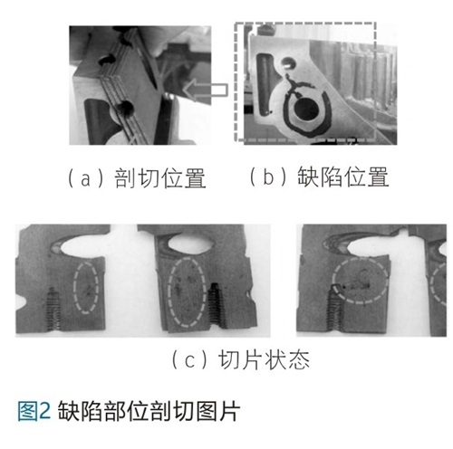
To investigate the cause of leakage in the oil gallery of the crankcase, a section was cut along the line connecting the Φ12mm oil gallery hole and the M8 bolt hole on the side of the leakage location. It was found that the defective area contained small shrinkage cavities and porosity in the thick-walled section, as shown in Figure 2. Due to the presence of internal porosity in the casting, subsequent machining of the oil gallery hole and M8 bolt hole destroyed the dense chill layer on the surface of the die casting, resulting in micro-leakage along the M8 threaded hole under a pressure of 600kPa.
2.2 Root Cause Analysis
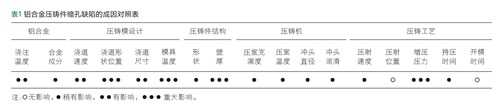
The key elements of die casting production are the die casting machine, die casting mold, and die casting alloy, and the die casting process organically combines these three major elements. Therefore, the factors affecting the quality of die castings include the die casting machine, die casting mold, die casting alloy, die casting process, and the structure of the die casting. A defect cause comparison table is used to analyze the causes of shrinkage cavities and shrinkage porosity in the crankcase from the above five factors. The cause comparison table for shrinkage cavity defects is shown in Table 1, where the gate position, intensification pressure, mold temperature, and casting wall thickness have significant influence.
Based on the analysis results of the cause table, the design of the mold gating system was re-evaluated to confirm that the defect location has a branch runner, which can meet the requirements of molten metal filling and the transmission of intensification pressure. Simulation software was used to conduct simulation analysis with different die-casting parameters, and the results showed that an isolated liquid phase zone consistently existed at the defect location, as shown in section A-A in Figure 3.
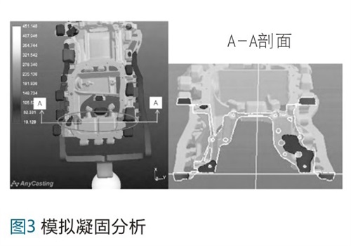
Based on the above analysis, it is confirmed that the root cause of the oil gallery leakage in the crankcase is the excessive local wall thickness of the casting. During the cooling process after die-casting, an isolated liquid phase zone forms within the casting. As this isolated liquid phase zone continues to cool, it cannot achieve pressurized feeding, ultimately resulting in shrinkage cavities and porosity.
3. Mold optimization design to address casting oil passage leakage
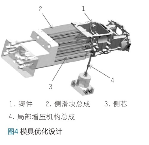
Based on the above root cause analysis of crankcase leakage, the die-casting mold was optimized with design measures including adding local intensification at the defect locations of the casting, adding cooling to small side cores such as the M8 pre-cast holes, and applying a "knurled texture" to the forming surface of the side slide, thereby eliminating the shrinkage porosity defects at the oil gallery holes. The structural design layout is shown in Figure 4.
3.1 Structural Design of the Local Pressurization Mechanism
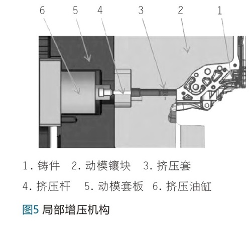
Local pressurization is a process in which, during the cooling of the casting after die casting, local extrusion is applied to the locations of isolated liquid-phase zones in thick and heavy sections of the casting. A hydraulic cylinder drives the extrusion rod to force the molten metal in the pre-stored space into the casting for feeding, making it an effective measure to solve shrinkage porosity caused by thick and heavy wall sections. The local pressurization structure of the crankcase is shown in Figure 5. Based on the structural shape of the defect locations in the crankcase, the local pressurization mechanism is designed in the moving die, and the extrusion cylinder is bolted to the rear end of the moving die sleeve plate. To prevent movement wear between the extrusion rod and the moving die insert from affecting fit accuracy, an extrusion sleeve component is designed. The extrusion sleeve is fixed to the moving die insert and maintains a fit clearance of 0.02 mm with the extrusion rod. Based on the volume of the isolated liquid-phase zone, the extrusion rod is designed with a diameter of 9 mm and a maximum extrusion stroke of 10 mm, and after extrusion it is flush with the cavity bottom surface. At a maximum extrusion pressure of 4500 kg/cm for the extrusion rod2The calculated extrusion cylinder diameter should be 50 mm.
3.2 Design of Lateral Core Cooling Water Structure
Based on the casting structure, the casting has 7 M8 threaded holes on the side in addition to the oil gallery holes. Due to the large number of M8 threaded holes and considering the influence of positional tolerance on the movable slide, the pre-cast hole core has a maximum forming diameter of 5.6 mm, which makes cooling of the core difficult. For the cooling of the small cores on the side slides in the crankcase die-casting die, a split-type cooling structure is adopted, and high-pressure purified water is used for single-point forced cooling of the cores.
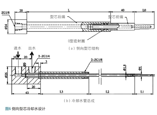
The split-type cooling structure is shown in Figure 6. The side core adopts a two-piece design. The front end of the core is made of SKD61, with a cooling water hole diameter of 2.8 mm at the forming area, machined by EDM hole drilling. The rear end of the core is made of H13, with a cooling water hole diameter of 6 mm. The front core and rear core are connected by M10×1 threads. The cooling water seal adopts an O-ring radial static seal, with the material selected as fluororubber or silicone rubber. It is required that no leakage occurs at an operating temperature of 200–250°C and an operating pressure of 15 atm.
The cooling water pipe adopts a spliced design. The inner spray pipe is spliced from white steel pipes with an outer diameter of 2.2 mm (inner diameter 1.8 mm) and an outer diameter of 4 mm, while the outer pipe uses 1/8′ galvanized pipe. As shown in Figure 6, during operation, cooling water enters the front end of the core from the rear through the inner spray pipe, and then returns through the gap between the outer wall of the inner spray pipe and the water channel hole of the core. To prevent blockage of the cooling water inside the small core, high-pressure purified water at 10 Bar is used to implement forced cooling of the small core.
3.3 Local machining of heat dissipation knurling on the side slider
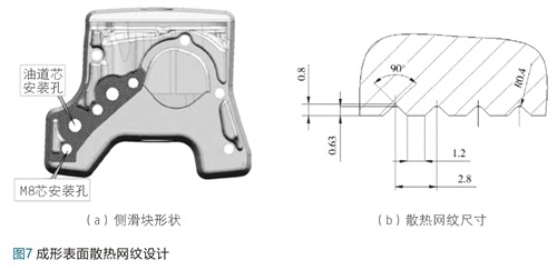
During the die casting process, high-temperature molten metal is injected into the cavity for forming and cooling, and the cavity is cooled through heat exchange with the die. The die casting die absorbs the heat brought by the high-temperature molten metal and dissipates it through die cooling and external spraying, so as to ensure the die remains in a state of thermal equilibrium. If the die temperature is too high, it will affect casting quality and die life. For specific local areas of the die, in addition to enhancing internal die cooling, the heat dissipation area can also be increased by enlarging the cavity surface area, thereby improving heat dissipation efficiency. At the oil gallery leakage location of the crankcase, because the local casting volume is large, die cooling and heat dissipation cannot reach a balanced state. Therefore, heat dissipation knurling is machined in the local high-temperature area on the forming surface of the side slide, with a knurl depth of 0.63 mm and arranged in a 90° cross pattern. The location and cross-sectional shape of the heat dissipation knurling are shown in Figure 7. The heat dissipation knurling is lower than the die forming surface and lies on the machined surface of the casting, and is removed during the subsequent machining of the side plane, requiring no additional process step.
4. Verification of the optimized design
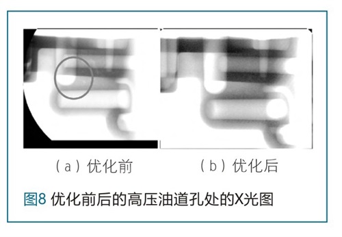
After the mold was optimized through the above three measures, die-casting production was carried out on the original production equipment using the original process parameters. Shrinkage cavities and porosity at the leaking areas of the oil gallery holes were significantly reduced, the chill layer on the wall of the M8 threaded hole became thicker, and the material became dense, with no through-wall shrinkage cavities or porosity in the casting. The mold was verified through mass production. After machining, the high-pressure oil gallery was tested at 600 kPa, and the product leakage rate was reduced to below 1%. The improvement in internal quality at the high-pressure oil gallery holes after mold optimization is shown in the X-ray comparison images in Figure 8.
5. Conclusion
(1) In aluminum alloy crankcase bodies, shrinkage cavities and shrinkage porosity defects occur at thick, heavy wall sections. If these shrinkage cavities and shrinkage porosity penetrate through to other machined holes, they will cause leakage in the casting.
(2) For localized thick walls in castings, isolated liquid zones may form during cooling. Applying localized pressurization to these areas can effectively reduce the formation of shrinkage cavities and porosity.
(3) Small cores can be cooled through a split-type cooling structure. To prevent fine water pipes from clogging, high-pressure purified water can be used to cool the cores.
(4) For specific areas of the mold, the cavity surface area can be increased by machining a textured pattern into the cavity, thereby enlarging the heat dissipation surface and improving cooling efficiency.

WeChat for technical support

PLUS Douyin