One-sentence answer: A millimeter-wave radar housing combines a radio-frequency radome and a rear housing via sealant or a seal strip. Water ingress corrodes the antenna board and degrades detection performance. Using a CTS Sentinel C28WE (C28) leak detector to perform a vacuum decay air tightness test on the radar housing enables factory rejection without damaging the radome or the antenna board.
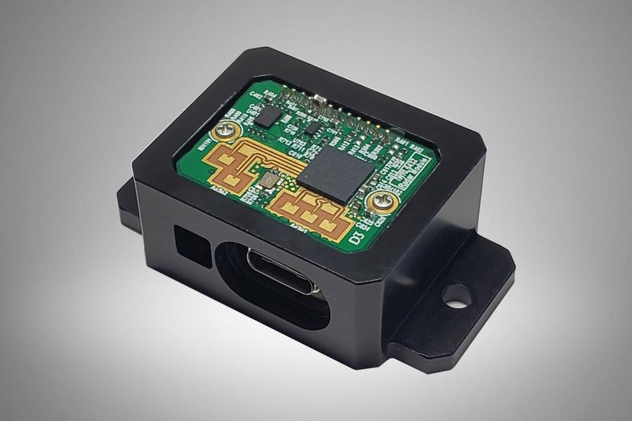
Radar housings must stay radio-transparent and sealed; breather membranes, connectors and housing joints are the main leak paths
The radome is made of radio-frequency transmissive material and cannot be metallized or contaminated. Sealing relies on the adhesive layer or seal strip on the rear housing side, and the flatness and warpage of the radome directly determine sealing quality.
The millimeter-wave antenna array and high-frequency substrate are extremely sensitive to moisture. A trace amount of moisture changes dielectric properties, manifesting as reduced detection range or lost targets, which is a functional-safety-related failure.
The housing needs to equalize internal and external pressure to prevent the seal from being crushed under temperature differential conditions. The venting structure itself forms a controlled channel and must be distinguished from a real leak during testing.
Sealing locations: the joint surface between the radome and the rear housing (sealant or seal strip), connectors and harness outlets, the venting structure, and the joint surface between the rear housing and internal brackets.Consequences of leakage: after moisture ingress, the antenna board and high-frequency substrate corrode or their dielectric properties drift, reducing detection accuracy and effective range; the risk of failure rises in rain or car wash scenarios, and the consequences are severe when safety functions such as automatic emergency braking are involved.
Because neither the radome nor the internal antenna board is suited to withstanding internal pressure. Vacuum decay establishes a pressure differential by drawing vacuum from the outside, avoiding radome deformation and internal pressure on the adhesive layer, making it more suitable for this type of precision electronic product.
The fixture uses a custom-formed soft rubber cavity to cover the outer surface of the radome, with evenly distributed contact pressure that does not scratch the radome. Pressing on the rear housing side should avoid the adhesive line and flatness-sensitive areas, preventing fixture pressure from becoming deformation interference on the sealing surface.
The venting structure produces a controlled slow pressure change. If the same criteria are used as for real leaks, normal venting is easily judged as a leak. Independent parameters should be set for the venting channel in the program, or the vent should be plugged in the specified manner before testing.
Yes, mainly the plugging method and deformation. The radome must not be metallized or scratched, so the fixture must use a soft custom-formed cavity with evenly distributed contact. The radome is often a thin-walled part that undergoes elastic deformation under pressure, so clamping force and test pressure differential must be frozen on the premise of not causing measurable deformation.
The core of air tightness testing for millimeter-wave radar housings is no internal pressurization, protection of the radome and antenna board, and independent definition of the venting channel. The CTS C28WE uses vacuum decay, ambient drift correction, and 32 programs to adapt to multi-model on-line testing, and together with custom-formed soft rubber fixtures, forms upstream assurance for radar reliability.

WeChat for technical support

PLUS Douyin