One-sentence answer: Sealing failure of a VFD housing allows dust and moisture to intrude, causing creepage and short circuits in power modules and busbars. With the CTS Sentinel I28 multi-function leak detector, multiple test stages can be run sequentially (in-series) within the same instrument to separately evaluate the air tightness of the large-volume cavity and the sealing of the busbar feed-through.
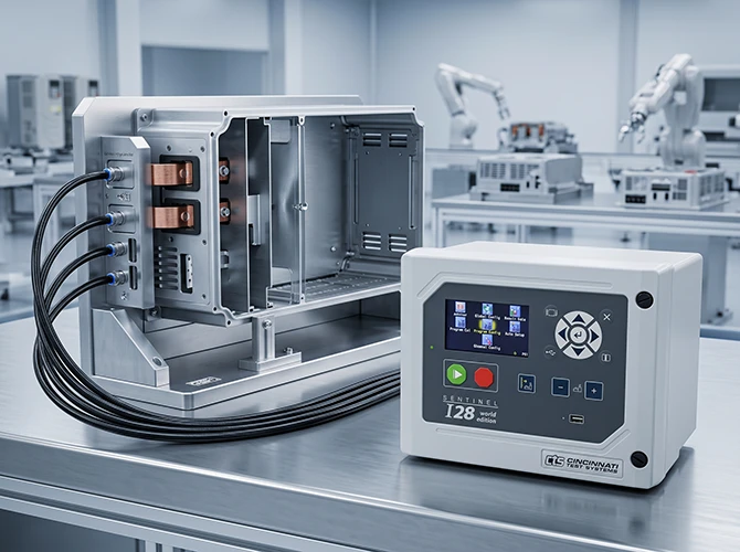
Cavity tightness and busbar feed-through sealing must both hold; reliability in dusty, humid plants depends on it
The enclosure is mostly sheet metal welded or assembled from profiles, with numerous weld seams and fastening points; accumulated micro-leaks at individual points likewise affect protection.
When high-power busbars pass through the housing, they rely on seals and compression structures; slight unevenness during assembly creates fine channels.
The larger the cavity, the slower the pressure stabilizes after inflation; applying a uniform cycle time leads to unstable readings.
Sealing locations: welded or riveted surfaces of the housing and end covers, seals where busbars and terminals pass through, the partition between the wiring cavity and the main cavity, and the isolation surface between the cooling air duct and the internal cavity of the cabinet.Consequences of leakage: moisture and dust intrusion cause busbar creepage, reduced insulation and short circuits; power modules and capacitors are contaminated, shortening their service life; communication between the wiring cavity and the main cavity allows external moisture to enter the electrical cavity directly.
Why multiple methods in series are essential here. VFD enclosures have two types of weak points: one is the large number of seams and fastening points formed by welding or riveting, where accumulated micro-leaks at individual points likewise affect protection; the other is where busbars and terminals pass through the housing, which relies on seals and compression structures, and slight unevenness during assembly creates fine channels. Both types of leak points are averaged out in an overall air tightness test, making it impossible to tell whether they come from long seams or from the feed-through. More challenging still is the volume effect of the large cavity itself: the larger the cavity, the slower the pressure stabilizes after inflation; if a uniform cycle time is applied, insufficient stabilization will treat pressure changes that have not yet stabilized as leakage. The reasonable approach is to first use pressure decay to evaluate the overall sealing of the housing and end covers, then program the busbar and terminal feed-through area as a separate stage, and finally use mass flow to confirm the isolation status between the wiring cavity and the main cavity.
The larger the cavity, the slower the inflation and stabilization; the cycle time depends on volume and stabilization requirements and must be calibrated by actual measurement of the workpiece—a fixed number of seconds cannot be applied. Once the calibration results are written into the test program, they can be called up by model without repeated trials.
Program the busbar and terminal feed-through area as a differential pressure decay stage for separate evaluation, recorded separately from the main cavity stage. This both locates the leak position and prevents reading fluctuations from the large cavity from masking local micro-leaks, making the conclusion more reliable.
Use a mass flow stage to evaluate the passage status between the two cavities. If a path exists where the two cavities should be isolated, this stage will give an abnormal conclusion, avoiding the problem of missing communication between the two cavities when only overall air tightness is tested.
Because a large volume requires a longer time to stabilize after inflation; insufficient stabilization misreads pressure changes that have not yet equalized as leakage. The purpose of calibration is to identify the conditions actually required for that specification to stabilize and fix them in the test program, so that readings for the same model are comparable and can be called up directly during changeover.
The key points for VFD housings are stable evaluation of the large-volume cavity and separate confirmation of feed-through sealing. The CTS Sentinel I28's multiple methods in series, temperature drift compensation and calibratable test programs make it suitable for batch factory sealing inspection of VFD enclosures.

WeChat for technical support

PLUS Douyin